Trying to fix Mega Drive game Streets of rage

Hello there
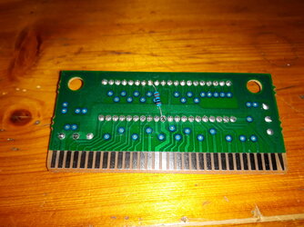
Is anyone familiar with fixing mega drive games that dont work with the 1k resistor fix?

have fixed few games in the past but i cant get this one to work,have changed also the cap and reflowed the chip,also checked for continuity and checks out.

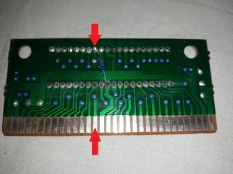
all the values i get with the multimeter in diode mode from the ground to the pins are 6 to 9 apart from the one on top i have soldered the resistor which is 0.2

Thank you!!
 

Attachments

  • 20230713_140457.jpg
    20230713_140457.jpg
    5.5 MB · Views: 91
It is often damaged traces or solder joints that are causing the issue. It would be necessary to trace the connections and conform to the original design. I often follow this method to repair SNES, SMS, and MD PCBs. I leave the original components intact, but it is often due to dry solder joints or damaged traces.
 
Use a voltmeter in Ohm mode, and you should have a maximum reading of 0.1 Ohm. If you have a higher reading, it means that a trace is severed or damaged. The naked eye may not be able to detect dry solder joints or micro cuts.
The copper and tin on these electronic circuits are old.


You need to do point-to-point wiring from the cartridge slot to the chip. Pay special attention to the contacts by following the traces, as well as any through-holes. Take a marker and note what is working correctly, for example, use black for good connections and red for problematic ones. Once you identify a fault, start by removing the old solder and apply fresh solder. If the circuit is still not closed, use a jumper wire as a last resort.
 
Last edited:
Use a voltmeter in Ohm mode, and you should have a maximum reading of 0.1 Ohm. If you have a higher reading, it means that a trace is severed or damaged. The naked eye may not be able to detect dry solder joints or micro cuts.
The copper and tin on these electronic circuits are old.


You need to do point-to-point wiring from the cartridge slot to the chip. Pay special attention to the contacts by following the traces, as well as any through-holes. Take a marker and note what is working correctly, for example, use black for good connections and red for problematic ones. Once you identify a fault, start by removing the old solder and apply fresh solder. If the circuit is still not closed, use a jumper wire as a last resort.
will try that,thank you very much!!
 
will try that,thank you very much!!
I think i have found the problem.. the bottom pin to the pin on top in diode mode the value is 0.08 (sometimes shows lower) the rest pins are from 8 to 9,these pins are connected cause i have used the multimeter in continuity mode,do i connect the pins with a jumper wire?
 

Attachments

  • 20230718_231721.jpg
    20230718_231721.jpg
    3.5 MB · Views: 66
Back
Top